How do I control a CNC machine from a 3D drawing?
From 3D drawing to CNC production: this is a crucial step in the modern manufacturing industry. Once you’ve designed a beautiful 3D model, of course you want to actually produce it. But how do you make sure your CNC machine understands exactly what needs to be made?
The transition from digital design to physical product requires the right software and knowledge of the production process. In this article, we answer the most frequently asked questions about controlling CNC machines from 3D drawings so you can successfully realize your designs.
What is the connection between 3D drawings and CNC machines?
3D drawings are the digital blueprint that is converted through CAM software into machine code (G-code) that CNC machines can interpret and execute. The CNC machine reads these instructions line by line and performs the operations to produce the physical part.
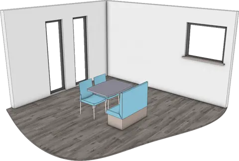
The process begins with a 3D model that contains all the geometric information: dimensions, shapes and material specifications. This digital information is then translated into a set of coordinates and motion instructions. The CNC machine uses these instructions to position tools and remove material according to the design.
The quality of the joint depends on several factors: the accuracy of the 3D model, the correct choice of material in the software and the correct machine settings. A good workflow ensures that what you design is actually producible within the capabilities of your CNC machine.
What software do you need to go from CAD to CNC?
You need both CAD software for 3D drawing and Computer-Aided Manufacturing (CAM) software to generate machining paths and produce G-code for your CNC machine. Many modern CAD packages include integrated CAM functionality.
CAD software such as SolidWorks, Fusion 360 or specialized solutions for the furniture industry is used to create the 3D model. CAM software takes this model and generates the actual machining strategy: which tools are used, in what order and at what speeds and feeds.
For optimal results, choose software that combines both functions. This avoids compatibility issues and ensures a seamless workflow from design to production. Also consider postprocessors that adapt generic G-code to the specific features of your CNC machine.
How do you generate G-code from a 3D model?
G-code is generated by defining machining operations on the 3D model in CAM software, selecting tools, setting machining parameters and then calculating the toolpaths to be followed by the CNC machine.
The process starts with importing your 3D model into the CAM software. Then you define the machining strategy: which surfaces to mill, where to drill holes and in what order. For each part, you select the right tool and set parameters such as cutting speed and throughput.
After calculating the toolpaths, the software checks for possible problems, such as collisions or unreachable areas. The final step is to generate the G-code with the appropriate post processor for your specific CNC machine. This code contains all motion instructions, tool changes and other machine functions.
What are the most common problems in CNC programming?
The most common problems are incorrect tool selection, incorrect machining parameters, tool/workpiece collisions and incompatible G-code due to incorrect postprocessor settings.
Tooling problems often arise from incorrect diameter or length specifications in the software. This leads to inaccurate dimensions or damaged tools. Machining parameters, such as excessive cutting speeds, can result in poor surface quality or broken tools.
Collision detection is crucial but often overlooked. While the software simulates tool movement, it does not always take into account clamps, fixtures or other obstacles in the workspace. Postprocessor problems cause the CNC machine to fail to interpret the code or execute it incorrectly.
Prevention starts with a thorough check of all settings before generating code. Always use the simulation function and check critical dimensions. Test new programs at low speeds first and stay with the machine during the first run.
How do you automate the process from 3D design to CNC production?
Automation is achieved by creating standardized workflows, setting up templates for frequently used operations and choosing software that automatically generates saw lists, material optimization and NC code from the 3D model.
Start by standardizing your design process. Use consistent naming, material specifications and machining methods. Create templates for standard operations, such as pocket milling, drilling or contour milling. These templates contain predefined tools and parameters.
Advanced automation includes feature-based machining, where the software automatically recognizes and applies operations. Think of automatic recognition of holes for drilling operations or faces for surface milling. Linking with ERP systems ensures that production orders are converted directly into CNC programs.
For maximum efficiency, look for software that automates the complete chain: from 3D model to saw lists, material optimization, NC code generation and even linking to your inventory system. This eliminates manual steps and significantly reduces errors.
How IronCAD helps with CNC programming
IronCAD offers a complete solution for the process from 3D drawing to CNC production, developed specifically for the manufacturing industry. The software combines powerful 3D design capabilities with integrated manufacturing output.
With IronCAD, you benefit from:
- Automatic generation of saw lists and NC code directly from your 3D model
- Integrated material optimization that minimizes waste
- The Para-Flex add-in developed specifically for wood, metal and plastic machining
- Seamless connection between design and production without additional conversions
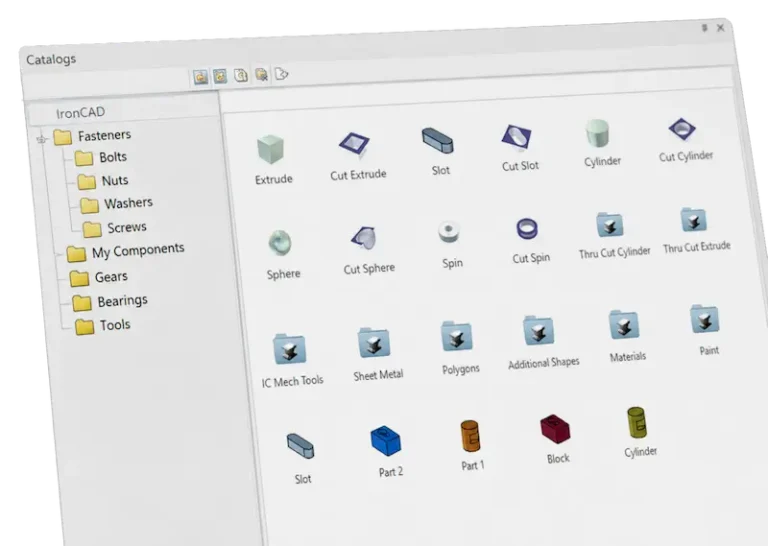
- An intuitive drag-and-drop interface that speeds up 3D drawing
Want to discover how IronCAD can automate your workflow from 3D drawing to CNC production? Contact us for a personal demonstration and tailored advice for your production process.