How do you incorporate joint details and finishing techniques into a 3D CAD design?
Incorporating joint details and finishing techniques into a 3D CAD design requires a systematic approach, combining accurate geometry with realistic material representation. By using advanced modeling tools and specific CAD functions, you can accurately represent complex joint joints and finishes, which is essential for a successful transition from design to production. If you have any questions about implementing these techniques in your design process, feel free to contact us.
Inaccurate joint details lead to costly production problems
When joint details are not worked out correctly in your 3D CAD design, miscommunications occur between design and production, leading to rework, material waste and delays. Production staff must make guesses about joint depths, angles and tolerances, resulting in inconsistent quality and higher costs. By accurately modeling joint details from the beginning and capturing all critical dimensions, you avoid these costly errors and ensure a smooth flow to machine shop or production.
Inadequate finishing specifications slow down the production process
Without clear finishing details in your 3D model, production teams must constantly feedback to the design team about material thickness, surface treatments and machining sequences. This causes production line downtime and significantly increases lead time. By specifying and visualizing finishing techniques directly in your CAD software, you create unambiguous communication that dramatically improves production efficiency.
What are joint details and why are they important in 3D CAD designs?
Joint details are the specific connection geometries between different parts in a 3D model, including tolerances, angles and distances. They determine how components are physically attached to each other and are critical to the structural integrity and production feasibility of the final product.
In metalworking and manufacturing, joint details are the basis for all machining processes. A correctly modeled joint contains information about weld seam preparation, bolt holes, clamp connections or bonding surfaces. These details determine not only the strength of the structure, but also which tools and machines are needed for production.
Joint details directly affect the costing of a project. Complex joint geometries require more machining time and specialized tools, while simple joints keep production costs low. By establishing joint details early in the design process, you can make conscious choices between functionality and production costs.
What finishing techniques can you model in 3D CAD software?
Modern CAD software supports modeling surface finishes such as sanding, polishing, anodizing, painting and electroplating through material libraries and surface properties. These techniques are visually represented and linked to production specifications.
Mechanical finishes such as milling, turning and grinding can be integrated directly into the 3D model. CAD systems allow you to add machining allowances, specify surface roughness and annotate critical dimensions. For kitchen construction, for example, specific edge finishes and laminate details are essential.
Thermal treatments and chemical finishes are usually specified via material codes and annotations in the model. You can associate hardening depths, corrosion resistance and other material properties to specific parts, which automatically flows through to production documentation and quality control.
How do you add accurate joint details to your 3D model?
Start by defining joint geometry by setting exact dimensions, angles and tolerances. Use parametric modeling to link joint details to the main geometry so that changes automatically propagate to all related parts.
Work with joint libraries that contain standard joints for your industry. These libraries provide consistency and speed up the design process. For welded joints, you specify weld preparation, including chamfer and root opening. For bolted connections, you define hole patterns, countersunk heads and required clearances.
Use assembly constraints to define the mutual positioning of components. This prevents interferences and ensures that all parts fit correctly. Add tolerance analysis to verify that joint details are within acceptable limits under normal production variations.
Which CAD tools are most effective for finishing details?
Surface modeling tools are essential for creating complex finish geometries. These features allow you to model smooth transitions, roundings and chamfers that represent actual finishes.
Feature-based modeling helps apply finishes systematically. You can define editing features such as grooves, reliefs and textures parametrically and reuse them in different designs. For interior design projects, these tools are indispensable for modeling decorative elements and finishing details.
Simulation tools within CAD software show how finishing techniques affect product behavior. You can perform stress analyses on welded joints or evaluate the influence of surface treatments on corrosion resistance. These insights help optimize both functionality and production costs.
How do you ensure that joint details are correctly transferred to production?
Use standardized drawing output automatically generated from the 3D model. Ensure that all joint details have clear dimensions, tolerances and machining instructions that are directly usable on the production floor.
Implement a PDM system that centrally manages all design information and provides version control. This prevents the use of outdated drawings and ensures that changes in joint details are automatically communicated to all those involved in the production process.
Automatically generate NC codes and machining instructions from the CAD model. Modern CAM integration ensures that joint details are translated directly into machine programs, eliminating the risk of interpretation errors. For complex projects in barn design, this automation is essential for accurate execution.
How IronCAD helps with joint details and finishing techniques
IronCAD offers an intuitive approach to modeling complex joint details and finishing techniques that perfectly meets the needs of the manufacturing industry. With our software you can:
- Create parametric joint geometries that automatically adjust with design changes
- Using extensive material and finishing libraries
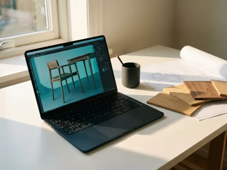
- Generate realistic visualizations that clearly show what the final product looks like
- Automatically generate production drawings and specifications from the 3D model
- Seamless integration with CAM software for direct machine control
Our training courses help your team make the most of these advanced features. Whether you’re working on simple weld joints or complex finishing details, IronCAD streamlines the entire process from design to production. Want to experience for yourself how IronCAD can improve your joint details and finishing techniques? Contact us for a personal demonstration.