How can I ensure that no errors occur during the transition from design to production?
You can prevent errors in the transition from design to production by managing design and production data in a single system, so that changes are automatically reflected in all related documents. This applies to any company in the manufacturing industry that works with custom-made or complex parts. In this article, we answer the most frequently asked questions about how to set up this process flawlessly.
Where does it go wrong between design and production?
Most errors occur when information is manually transferred from the design phase to production preparation. Think of retyping dimensions into an Excel file, exporting individual drawings that no longer match the latest version, or using multiple files that aren’t synchronized with each other. Every manual step is a potential source of error.
Specifically, we see this in situations such as:
- A designer adjusts a measurement, but the cutting list has already been exported and is not updated
- Production is working with an older version of a drawing because there is no clear version control system
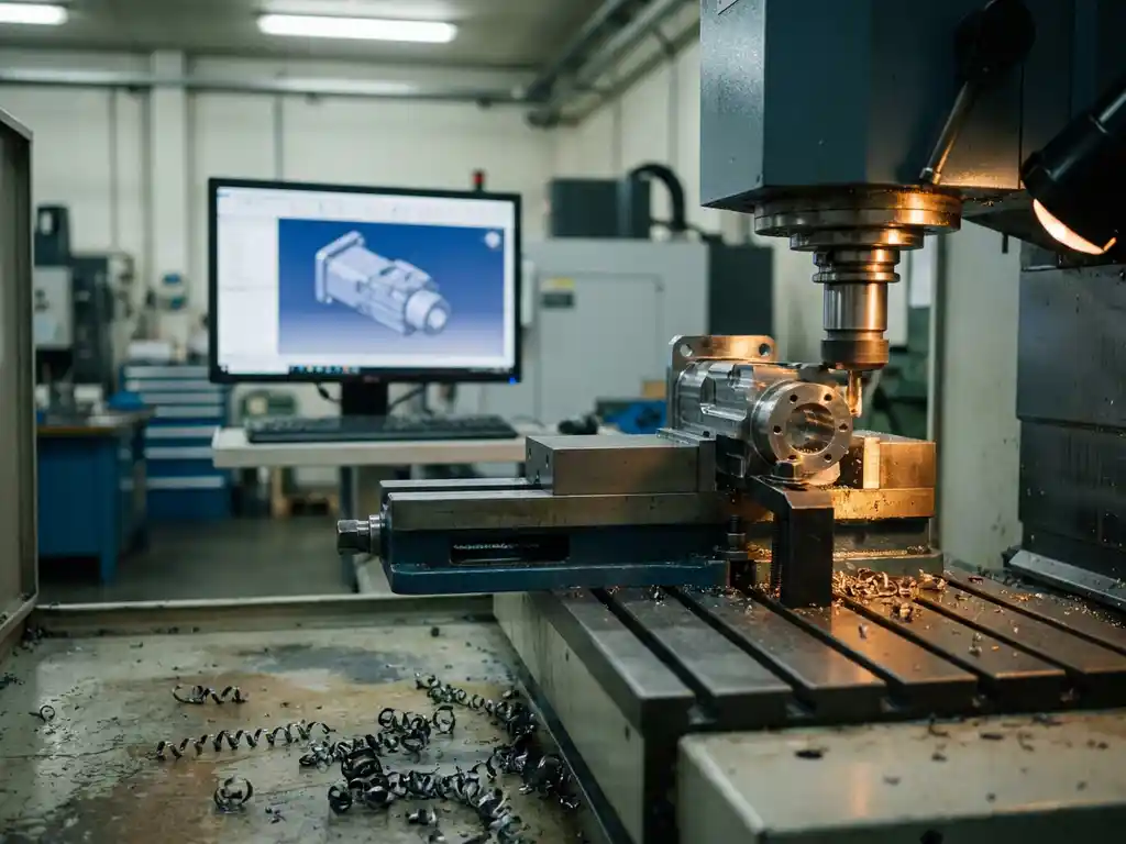
- The dimensions are correct on the drawing, but the conversion to NC code contains an error due to a manual data entry step
- Purchasing lists are created separately and do not automatically align with the 3D model
The more separate steps and tools you use, the greater the chance of errors. The solution lies not in more post-processing checks, but in fewer manual transfers beforehand.
What are the consequences of errors in production planning?
Errors in production planning directly result in a waste of materials, time, and money. An incorrect dimension in a cutting list can render an entire sheet of sheet material unusable. An error in the NC code can damage a machine or render a batch of products unsuitable for use.
The consequences often extend beyond the mistake itself:
- Delivery times are being extended because parts need to be remanufactured
- Material costs are rising due to unnecessary scrap and rework
- Customer confidence declines when products do not meet the agreed-upon specifications
- Employees waste time tracking down and fixing errors instead of doing productive work
For companies that specialize in custom work, such as those in the furniture and interior design industries, these consequences are particularly acute. Every product is different, which means that every error is unique and cannot be easily resolved with a standard solution.
How does an integrated CAD solution ensure error-free output?
An integrated CAD solution eliminates manual transfer steps by generating all production outputs directly from the 3D model. Cutting lists, bill of materials, reports, and NC codes are automatically generated based on the current design. If you modify the model, all outputs are updated immediately.
Here’s how it works in practice:
- The 3D model is the single source of truth. All documents are linked to it.
- Changes to the design are automatically applied to cutting lists, parts lists, and NC programs
- Sheet optimization is calculated automatically, which also reduces material waste
- NC codes are generated directly from the model, without manual entry
As a result, production planning no longer depends on the accuracy of an employee who enters data, but on software that does so automatically and consistently. Check out the available CAD solutions if you want to see what output options are available.
What role does parametric design play in preventing dimensional errors?
Parametric design prevents dimensional errors because all dimensions and proportions in a model are linked to one another via parameters. If you change a single dimension, all dependent dimensions adjust automatically. You never have to manually update multiple locations in a drawing.
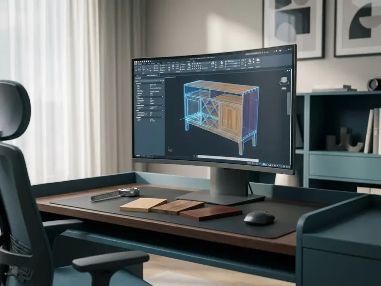
This is especially valuable for custom work. Suppose you’re designing a kitchen cabinet that’s available in three widths. With parametric design, you create a single model with variable parameters for width, height, and depth. If you select a different width, the hinge positions, screw holes, and panel divisions automatically adjust accordingly.
Without parametric design, you have to check whether all dimensions are still correct for each variant. Not only is this time-consuming, but it’s also a systemic source of errors. With parametric design, that check is built right into the model itself.
When does it make sense to integrate CAD and ERP?
Integrating CAD and ERP makes sense as soon as you notice that information from your designs is being entered manually into your order or inventory management systems. At that point, two parallel information flows are created that are not automatically synchronized, leading to errors in purchasing, planning, and invoicing.
A link is particularly valuable in the following situations:
- You work with customer-specific products where the bill of materials varies by order
- Purchasing requirements are directly determined by what is specified in the design
- Production planning depends on the complexity of the design
- You want to prevent buyers from working with outdated bill of materials
By integrating CAD and ERP, information flows automatically from design to order, procurement, and production. This not only saves time, but also prevents the errors that arise when people have to enter the same information in multiple places. For companies across a wide range of industries, this integration is a logical step toward a fully automated production process.
How quickly can employees learn to use new CAD software?
With modern CAD software, employees typically learn the basics within a few days, not a few months. The learning curve depends heavily on how intuitive the software is and the quality of the available training. Software designed with a low barrier to entry for new users ensures that engineers can become productive quickly.
A few factors that accelerate adoption:
- Intuitive interface: software that lets you work directly in 3D without having to set up a complex structure first
- Targeted Training: Customized CAD training courses tailored to your industry and work methods
- Good support: access to support when employees get stuck during their first few weeks
- Step-by-step implementation: Start with the most frequently used features and expand as the team gains more confidence
It’s a misconception that switching to new software always means months of downtime. With the right guidance and software tailored to the manufacturing industry, employees can start working independently surprisingly quickly.
How IronCAD Helps Ensure Error-Free Production Output
IronCAD is the CAD solution we offer at Dynfos for companies in the manufacturing industry that want to move from design to production without errors. The software is specifically designed to eliminate the manual steps between design and production. Here’s what IronCAD does for you, in concrete terms:
- Automatic generation of cutting lists, parts lists, and NC codes directly from the 3D model
- Parametric design, in which changes to dimensions are automatically reflected in all dependent elements
- Sheet optimization that minimizes material waste and can be exported directly to the machine
- Integration with ERP to ensure that design and business processes align seamlessly
- A steep learning curve that gets your team up and running in a matter of days, not months
Would you like to know how IronCAD fits into your production process? Contact us for a no-obligation consultation. We’d be happy to work with you to figure out how to make the transition from design to production seamless.