How do you convert a production drawing to a stacking instruction for the workshop?
Converting a production drawing into a stacking instruction requires a systematic approach in which you translate technical information into practical work steps. You analyze the drawing, identify all required actions and convert them into a logical sequence that employees can follow. If you have questions about optimizing this process, you can always contact us.
Unclear work instructions cause costly production errors
When stacking instructions are not clear or miss important details, employees make mistakes that lead to downtime, rework and delayed deliveries. These errors not only cost material and time, but also damage customer relations. The solution lies in structurally analyzing your production drawings and systematically converting them into detailed, visually supported work instructions that leave no room for interpretation.
Outdated instructional methods inhibit your production efficiency
Manually creating stack instructions in static documents creates inconsistencies and makes updates time-consuming. Employees lose time due to ambiguities and misinterpretations of 2D drawings. By employing modern CAD software, you can automatically generate 3D visualizations, link instructions to production data and make real-time updates that are immediately available on the shop floor.
What is the difference between a production drawing and a stacking instruction?
A production drawing shows the end result with technical specifications, while a stacking instruction describes the execution. The drawing includes dimensions, tolerances and material specifications, but the instruction tells employees step-by-step how to make the product.
Production drawings are technical documents designed for engineers and quality personnel. They contain complex information such as cross-sections, detail views and technical annotations. Stack instructions, on the other hand, are practical documents for implementation. They translate the technical information into concrete actions: what tools to use, in what order to work and what to pay attention to during production.
The difference is also in presentation. Drawings use standard CAD symbols and projection methods, while instructions use visual aids such as 3D renders, photographs and flow charts to clarify execution. For complex products in mechanical engineering, one drawing can result in dozens of detailed work steps.
How do you analyze a production drawing to create work instructions?
Begin by identifying all parts and their interrelationships. Then determine the logical sequence of operations and identify critical points where special attention is needed. For each step, note all tools, materials and quality controls required.
Start your analysis by identifying the main components and understanding their function. Review which components must be assembled first and what dependencies exist. Note tolerances and critical dimensions that require extra attention during production.
List all operations required: cutting, drilling, welding, assembling and finishing. Group similar operations and determine the most efficient sequence. Identify points where quality controls are needed and where employees often make mistakes. This analysis forms the basis for your structured stacking instruction.
What information should you include in a stacking instruction?
A complete stacking instruction contains the work steps in logical sequence, the materials and tools required, safety instructions, quality controls and visual support. Each step must be specific and executable, with no room for interpretation.
Structure your instruction with clear sections:
- Material list with specifications and quantities
- Tool list with settings where relevant
- Safety instructions and personal protective equipment
- Detailed work steps with time indications
- Quality control points and acceptance criteria
- Troubleshooting tips for common problems
For industries such as kitchen construction, visual elements are crucial. Include 3-D renderings, exploded views and detail photos that clarify work steps. Use standard terminology and avoid jargon that not everyone understands. Make sure each step is verifiable so employees can check that they are working correctly.
How do you use CAD software to create stack instructions?
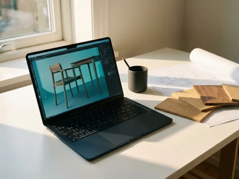
Modern CAD software can automatically generate exploded views, cross-sections and 3D visualizations perfect for stacking instructions. You can create animations of assembly sequences and link technical data to visual elements for interactive instructions.
Start by creating exploded views that show how parts come together. Use animation features to visualize assembly sequences and create cross-sections that clarify internal structures. Many CAD packages can automatically generate parts lists that you can use directly in your instructions.
Link production data to your 3D models so that instructions are automatically updated as your design changes. This is especially valuable in metalworking, where specifications change frequently. Export various views and detail shots that illustrate specific operations. This way you create visually rich instructions that are much clearer than traditional 2D drawings.
What are common mistakes when converting drawings to instructions?
The most common mistakes include skipping preparatory steps, an unclear sequence of operations, missing safety instructions and using technical jargon that employees do not understand. They also often forget to include quality controls.
Many instructions fail because they remain too technical and are not written from the performer’s perspective. Employees need concrete, actionable steps, not technical descriptions. Another common mistake is that instructions are not tested with field employees before they become final.
Avoid these problems by:
- Have instructions reviewed by experienced staff
- Test each step for feasibility
- Add clear visual support
- Regularly gather feedback and update instructions
- Use standard terminology that everyone understands
Also be careful not to cram too much information into one step. Complex operations should be broken down into smaller, manageable parts. For interior design projects, this often means dividing up assembly sequences by room or functionality.
How IronCAD helps create stack instructions
IronCAD offers powerful tools to automatically generate visual instructions directly from your 3D models. The software can produce exploded views, animations and technical documentation perfect for workshop instructions. Integrated features allow you to:
- Automatically generate exploded views for assembly instructions
- Create 3D animations that clarify complex operations
- Linking technical data to visual elements
- Automatically generate and synchronize parts lists
- Export different views for detailed instructions
- Implement updates that automatically update all related documents
IronCAD’s intuitive interface lets you quickly create professional instructions without extensive CAD knowledge. The software integrates seamlessly with manufacturing processes and ensures that your instructions always remain current. Want to experience how IronCAD can improve your instructional process? Contact us for a personal demonstration.