What CAD software supports composite design for the manufacturing industry?
CAD software for composite design requires specialized features such as layer construction, fiber orientation management and material property simulation. Traditional CAD programs are designed for metals and plastics, but composite materials have unique design requirements that necessitate specific tools. If you have questions about the right software choice, you can always contact us.
Missing composite features significantly slow down your design process
When you design composite parts with standard CAD software, you run into fundamental limitations. You cannot define layer structures, visualize fiber directions or simulate material properties. This means you have to constantly switch between different programs, make manual calculations and discover errors late in the process. The result: longer lead times and higher development costs. The solution lies in CAD software with built-in composite functions that streamline the entire design process.
Incompatible manufacturing dates create costly production errors
If your composite design is not directly translatable into production instructions, dangerous communication gaps occur. Production engineers must manually interpret design drawings, estimate fiber directions and work out the layer structure themselves. This leads to material waste, quality problems and expensive remanufacturing. You need CAD software that automatically generates production data: cut lists for composite layers, fiber orientation maps and optimized material layouts.
What is composite design and why is specialized CAD software needed?
Composite design is the design process for parts made from fiber-reinforced materials such as carbon fiber, fiberglass or aramid. It requires specific CAD functions because composites consist of multiple layers with different fiber orientations and material properties that traditional CAD software cannot manage.
Unlike metal parts, composites have a complex internal structure. Each layer has a specific fiber orientation, thickness and material property. These parameters determine the strength, stiffness and weight of the final product. Standard CAD programs treat materials as homogeneous blocks, which is insufficient for composite design.
Specialized CAD software provides tools for layer construction, fiber orientation management and simulation of material properties. This prevents design errors and significantly reduces the time from concept to production.
What CAD functions are essential for composite design?
Essential CAD features for composite design include layering tools, fiber orientation management, a material properties database, drapery simulation and automated generation of cut lists. These features allow you to accurately design complex composite structures and translate them directly into production instructions.
Layering tools let you define each composite layer individually with a specific thickness, material type and fiber orientation. This is crucial because the order and orientation of layers determine the mechanical properties of the part. Without this functionality, you cannot make reliable strength calculations.
Fiber orientation management visualizes how fibers flow through the part, which is especially important for complex 3D shapes. Drapery simulation shows how composite layers behave when laid over a mold, which helps identify folds or stresses.
Automated generation of cut lists instantly creates production instructions with exact dimensions, shapes and fiber directions for each layer. This eliminates manual interpretation and reduces the chance of production errors.
How does IronCAD support composite design in the manufacturing industry?
IronCAD supports composite design with a flexible 3D design environment that can manage complex layer structures, provides parametric material modeling, and integrates directly with manufacturing systems. The software treats composite layers as separate objects that you can manipulate, visualize and optimize within a single design environment.
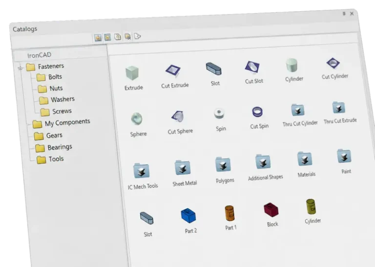
IronCAD’s catalog-based approach is ideal for composite design because you can store and reuse standard layer builds. This speeds up the design process and ensures consistency across projects. For example, you can define a standard carbon fiber layer structure for mechanical engineering applications.
Parametric capabilities let you quickly calculate variants by adjusting bearing thickness or fiber directions. Changes are made automatically throughout the design, saving time in optimization iterations. For metalworking companies switching to composites, this offers a familiar design experience.
What is the difference between CAD software for composites and traditional materials?
CAD software for composites treats materials as built-up structures with directional properties, while traditional CAD software considers materials as homogeneous blocks with uniform properties. This fundamental difference requires completely different design tools and workflows.
Traditional CAD software defines a part based on its geometry and assigns material properties to it. For steel, for example, this means a density of 7850 kg/m³ and a tensile strength of 400 MPa in all directions. These values are constant regardless of the direction in which you measure.
Composite CAD, on the other hand, must manage each layer separately. For example, a carbon fiber layer has a tensile strength of 3,500 MPa in the fiber direction, but only 50 MPa perpendicular to it. The software must be able to model these anisotropic properties and perform calculations that take into account the orientation of each layer.
Moreover, composite CAD generates other outputs: instead of machining drawings for stable equipment, it produces cutting patterns, layer sequences and draping instructions that are directly usable for composite production.
How do you integrate composite design with manufacturing processes?
Integrate composite design with production processes by choosing CAD software that automatically generates production data: cut lists, layer sequences, material requirements and NC codes for cutting machines. This direct link between design and production eliminates manual translation steps and reduces the risk of errors.
Integration starts with material definition in the CAD software. You define not only mechanical properties, but also production parameters such as roll width, material costs and cutting speeds. The software later uses this information for automatic optimization of material usage and production time.
Modern CAD systems instantly generate cutting patterns optimized for minimal material loss. They take into account fiber directions, material widths and nesting efficiency. For complex parts, they can automatically compare multiple cutting strategies and select the most efficient one.
The output integrates seamlessly with ERP systems for material planning and with CAM software for automated production. This creates a continuous workflow from design to final product, which is essential for competitive composite manufacturing.
How IronCAD helps with composite design
We offer a complete solution for composite design in the manufacturing industry with IronCAD. Our software combines intuitive 3D design tools with specialized composite functions, allowing you to easily design complex layer structures and translate them directly into production instructions.
The benefits of IronCAD for composite design:
- Flexible layering with visual control of fiber directions
- Parametric material modeling for rapid design iterations
- Automatic generation of cutting lists and production instructions
- Seamless integration with our ERP solution for complete workflow automation
- Extensive materials library with composite properties
Whether you’re working on parts for kitchen construction or interior design with composite panels, IronCAD provides the tools you need. Want to experience for yourself how IronCAD can improve your composite design? Contact us for a personal demonstration.