How can I ensure that the workshop can extract all the necessary information directly from my drawing?
The workshop can extract all the necessary information directly from your drawing if you specify in advance which data should be included and use CAD software that automatically generates this information. This includes dimensions, material specifications, machining instructions, and bills of materials. The better your drawing is structured, the less room there is for errors or misunderstandings on the shop floor. In this article, we answer the most frequently asked questions about shop floor information and drawings.
What information does the workshop need from a drawing?
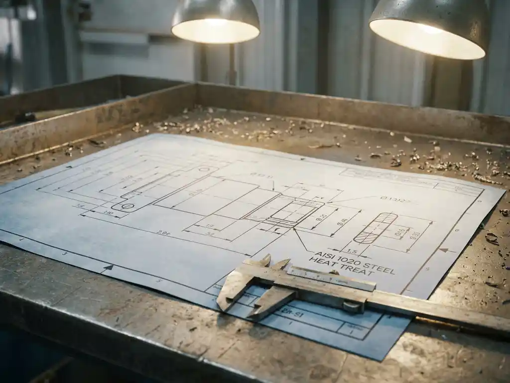
A good working drawing must include, at a minimum, dimensions, material specifications, tolerances, surface finishes, and machining instructions. Without this basic information, the shop cannot properly execute the design. Depending on the manufacturing process, additional data may be required, such as cutting lists, NC codes, or assembly sequences.
Specifically, the repair shop needs the following information:
- Dimensions and Tolerances: Exact Dimensions and Permissible Deviations
- Material Specifications: type of material, thickness, quality, and any coating
- Processing Instructions: Which operations must be performed and in what order
- Parts Lists: An Overview of All Components, Quantities, and Part Numbers
- Cutting and trimming guides: for efficient material layout and minimal waste
- NC codes: for CNC machines that are controlled automatically
- Assembly Drawings: How Individual Parts Come Together to Form a Final Product
The more complex the product, the more information the drawing must contain. For custom-made furniture, cutting lists and sheet metal optimization are essential. In metalworking, on the other hand, tolerances and welding specifications are crucial.
How do you ensure that all that information is automatically extracted from your CAD drawing?
You ensure that information is automatically extracted from your drawing by working with parametric 3D CAD software linked to a database of materials, parts, and operations. As soon as you create a design, the software automatically generates bills of materials, cutting lists, and production reports based on the parameters you’ve entered.
The key lies in how you build your models. If you name parts correctly, assign material properties, and define operations within the model itself, you won’t have to manually retype that information later. This not only saves time but also eliminates the risk of errors that arise during manual data transfer.
Practical steps to achieve this:
- Work with a standardized library of parts and materials
- Assign material properties to each part in your model
- Use templates for recurring product types
- Let the software automatically generate parts lists and cutting lists
- Export NC codes directly from the model to the machine
What is the difference between a working drawing and a production drawing?
A working drawing shows what a part or product looks like, including all dimensions and specifications. A production drawing goes a step further and also contains the information needed to actually manufacture the product: machining sequences, machine settings, cutting lists, and NC codes. A production drawing is essentially a working drawing supplemented with process information.
In practice, these terms are sometimes used interchangeably, but the distinction is important. A designer creates a design drawing to document the design. The production planner or process engineer then translates that design drawing into a production drawing that the shop floor can use directly.
In modern CAD environments, these boundaries are becoming increasingly blurred. Good software generates both types of documents from the same model, ensuring that no information is lost during the transition from design to production.
Why does the workshop sometimes not understand a drawing?
The workshop cannot interpret a drawing if information is missing, if the drawing is inconsistent, or if the symbols and standards used are unfamiliar to the workers carrying out the work. A lack of context—such as the absence of an elevation or a cross-section—also leads to confusion and errors.
The most common causes of miscommunication through drawings are:
- Missing dimensions: Not all dimensions are marked on the drawing, forcing the workshop to guess or ask for clarification
- Unclear symbols: Not everyone is familiar with standards for surface finishes or welding
- Outdated drawings: The workshop is using an older version that is no longer current
- Too few views: a 2D drawing does not provide sufficient spatial insight
- No context: individual parts without an assembly drawing lead to incorrect assembly
The solution starts with discipline in the drafting process: use standard templates, review drawings before approval, and implement a clear version control system. Including a 3D model along with the 2D drawing significantly reduces spatial confusion.
How does 3D CAD software help improve communication with the shop floor?
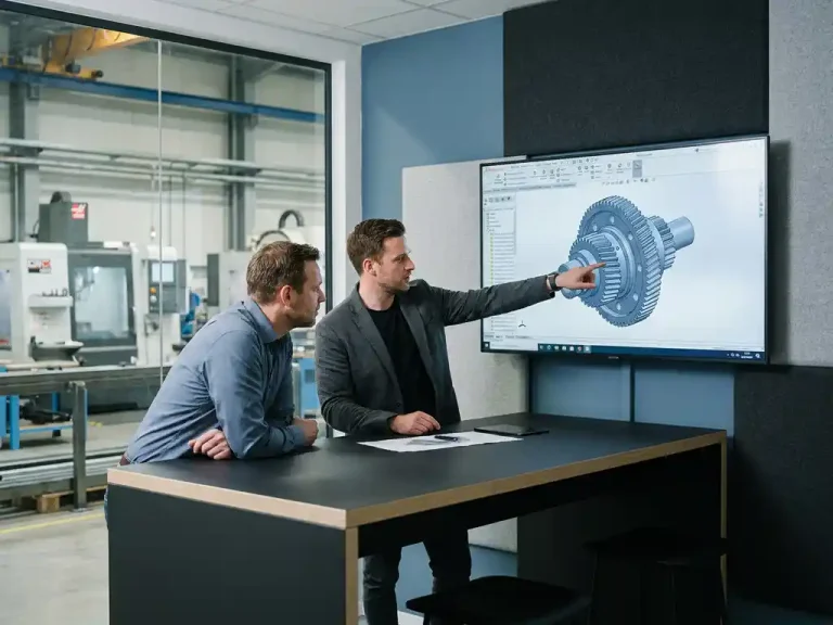
3D CAD software improves communication with the shop floor because a three-dimensional model is much more intuitive to understand than a traditional 2D drawing. Employees can immediately see what a part looks like, how it fits into the bigger picture, and what machining operations are required. In addition, 3D software automatically generates consistent 2D views from the same model.
With 3D CAD software, you can enjoy a number of concrete benefits for shop floor communication:
- Spatial perception without interpretation: everyone sees the same thing
- Automatically generated views and cross-sections that always match the model
- Direct link between the model and the bill of materials, so that changes are automatically reflected
- Export options to PDF, DXF, or directly to CNC machines
- Fewer rework requests and corrections during production
Would you like to know which CAD software solutions are best suited to your production process? On our products page, you’ll find an overview of the available options.
When is it a good idea to integrate CAD and ERP software?
It’s a good idea to integrate CAD and ERP software as soon as you notice that information from drawings is being manually transcribed into orders, purchasing, or production planning. That manual step is time-consuming and prone to errors. An integration ensures that bills of materials, material lists, and operations are automatically fed into your business processes.
Specifically, a link is valuable when you’re dealing with:
- Large numbers of variants or custom orders
- Complex bills of materials with many parts and semi-finished products
- Procurement that depends on what is included in the design
- Production planning driven by customer orders
- Inventory management directly linked to the materials in your designs
For smaller companies with simple products, a standalone CAD environment is often sufficient. But as complexity increases, an integrated approach quickly pays for itself through fewer errors, shorter lead times, and better insight into costs and progress. See also which industries such integration is most relevant for.
How IronCAD Helps You Extract Shop Floor Information Directly from Your Drawing
IronCAD is a powerful 3D CAD solution that is particularly well-suited for companies in the manufacturing industry that want to work quickly and accurately. The software was developed with real-world shop floor operations in mind and automatically generates all the output you need to move from design to production.
Here’s what IronCAD actually does for you:
- Automatic parts lists and cutting lists generated directly from the 3D model
- Sheet optimization for minimal material waste and lower procurement costs
- Export NC code directly to CNC machines, without an intermediate step
- An intuitive interface that you can master in just a few days, not after months of training
- Flexible design without restrictive history structures, even when changes are made later
- Seamless integration with ERP software for a fully integrated production process
Whether you work in furniture and interior design, metalworking, or mechanical engineering, IronCAD ensures that the workshop always has the right, up-to-date information. Would you like to see how this works in your situation? Contact us for a no-obligation demo.