How can I make custom metal structures more efficient?
You can make custom metal structures more efficient by seamlessly integrating the design and production processes: from 3D model to flat pattern, from bending data to NC code, without any manual intermediate steps. For companies in the metalworking and sheet metal fabrication sector, time savings and accuracy go hand in hand when software automates the transition from design to production. In this article, we answer the most frequently asked questions about how to put this into practice.
Which steps take the most time when designing metal structures?
The biggest time-wasters in the design of metal structures are manually converting 3D models into production drawings, calculating flat patterns, and correcting errors that only come to light on the shop floor. It is precisely these steps that are repeated with every custom project, causing unnecessary delays.
Specifically, these are the steps that take the most time in practice:
- Manually creating production drawings based on a 3D model, requiring each design change to be reapplied to the drawing
- Calculating bending allowances and flat-pattern dimensions, where errors in angles or radii do not become apparent until later in the process
- Communication between the design department and the workshop, in which information is lost or misinterpreted
- Verifying manufacturability, since not every design can be produced without modifications
In custom projects, where every component is unique, this problem is exacerbated. There is no standard template to fall back on, which means the designer has to go through the same manual steps all over again for every project. Automating these steps therefore yields the greatest time savings.
How do you automatically convert a 3D model into a flat pattern?
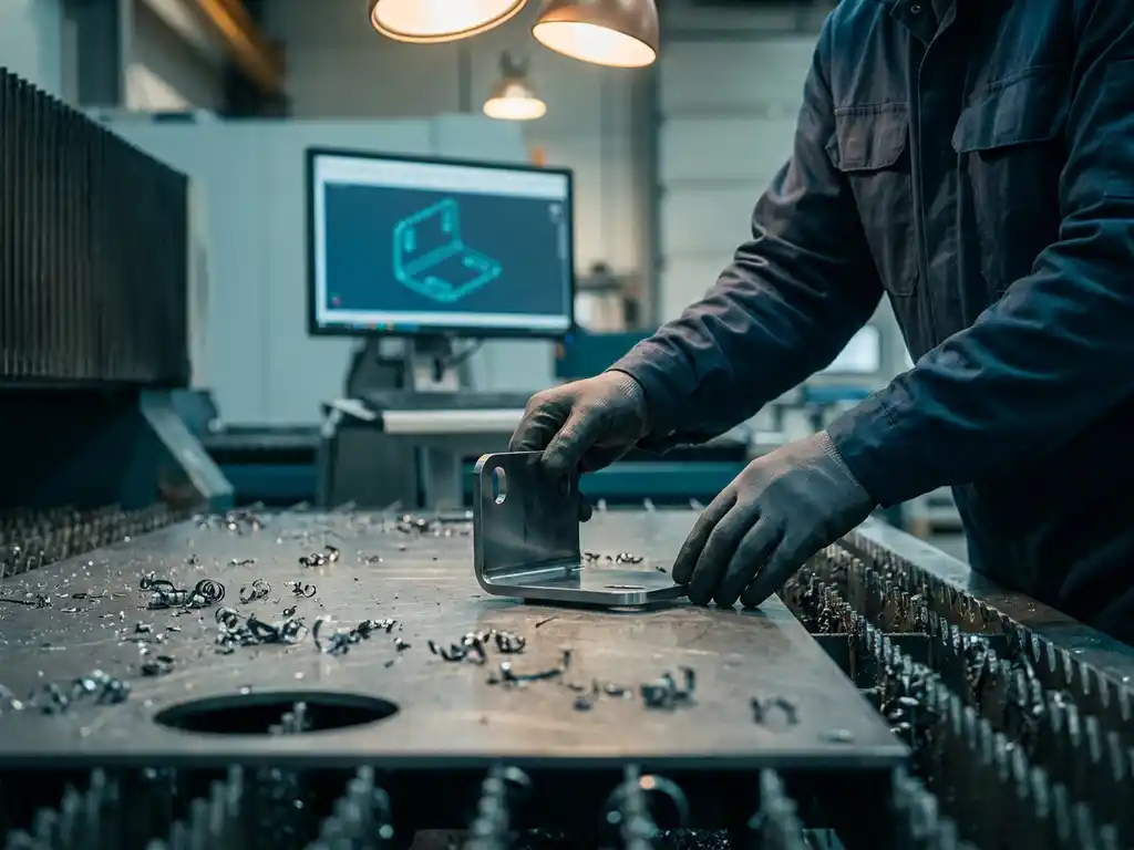
A 3D model is automatically converted into a flat pattern by CAD software that incorporates bend allowances, material thickness, and bend radii into an integrated calculation model. Once the 3D model is ready, the software generates the flat pattern, including cutting lines and bending information, without requiring you to calculate these manually.
The key lies in how the model is constructed. When you model sheet metal with the correct material properties and bending parameters, the software knows exactly how the material behaves during bending. The result is not a separate calculation performed afterward, but a direct derivative of the 3D model itself.
In practical terms, this means:
- Layout lines are generated automatically and are immediately readable by the workshop
- Bend information such as angle, radius, and direction is linked to the model
- Changes to the 3D model are automatically reflected in the results
- The results can be used immediately for laser cutting, punching, or waterjet cutting
This eliminates one of the most error-prone steps in the sheet metal manufacturing process: the manual conversion from 3D to 2D.
What is the difference between parametric and direct modeling in sheet metal fabrication?
In parametric modeling, you work with fixed relationships and rules between components: if you change one dimension, the rest of the model adjusts automatically. In direct modeling, you freely adjust the geometry without any underlying rules, which provides more flexibility but results in fewer automatic updates when changes are made.
Parametric Modeling
Parametric modeling is ideal for mass production and families of similar parts. You define the design logic once and then simply adjust the parameters. In sheet metal design, this means that you position a bend or hole once relative to a reference point, and the position automatically adjusts when dimensions change. This saves a lot of time on repetitive designs.
Direct Modeling
Direct modeling offers more freedom when working on complex or organic shapes, or when you want to modify an existing model without knowing its construction history. You pull, push, and move geometry directly, which is intuitive but less suitable for designs that require consistent dimensional changes. For custom metal fabrication, a combination of both approaches is often the most practical.
How can you prevent errors during the transition from design to production?
You can prevent errors during the transition from design to production by making the flow of information between the designer and the shop floor as short and automated as possible. The fewer manual steps there are between the model and the production data, the lower the risk of interpretation errors, outdated drawings, or incorrect dimensions.
The most common causes of errors in this process are:
- Drawings that are not up to date following a design change
- Bending allowances that are calculated manually and do not match the actual material response
- Missing or unclear setup instructions on the shop floor
- NC codes that are created manually based on the drawing rather than the model
The solution lies in working from a single central model from which all production data is automatically generated. When the drawing, the layout, the cutting list, and the NC code all come from the same model, there is no room for version conflicts. A change in the design is immediately reflected in all output, ensuring that the shop floor always works with the most up-to-date information.
In addition, it helps to verify manufacturability as early as the design stage. Check bend radii in relation to the material thickness, ensure minimum distances between holes and outer edges, and verify that the final part fits within the available sheet size. The earlier these types of checks are performed, the less expensive it is to make corrections.
Which CAD software is suitable for custom metalworking?
CAD software suitable for custom metal fabrication combines powerful 3D modeling with integrated sheet metal tools: automatic blanking, bending calculations, and direct integration with production data. The software must be both technically accurate and flexible enough to efficiently handle single-piece and small-batch production.
What to Look for When Choosing CAD Software for Metalworking:
- Sheet Metal Environment: specific tools for bends, flanges, and cutting lists that are integrated into the modeling environment
- Flexibility: Support for both parametric and direct modeling, allowing you to quickly switch between custom and repetitive designs
- Production output: direct generation of NC codes, DXF files, and cutting lists without the need for intermediate software
- Scalability: suitable for single-unit production, but also efficient for larger production runs
- Ease of use: an intuitive interface that helps designers get started quickly without a steep learning curve
In addition to technical capabilities, the support provided by the vendor is also important. Implementation, training, and ongoing support all play a role in determining how quickly a team becomes productive with new software.
How do you integrate CAD software with your production process and ERP?
You can integrate CAD software with your production process and ERP by automatically making the CAD system’s output—such as bills of materials, material lists, and NC codes—available in your ERP environment. This prevents duplicate data entry, reduces the risk of errors, and streamlines the flow of information from design to delivery.
In practice, a good integration means the following:
- Bill of materials from the CAD model are automatically imported into the ERP system for procurement and production planning
- Material consumption and sheet optimization are reported in real time, ensuring that purchase orders match actual needs
- Work orders in the ERP system contain the correct technical information without anyone having to enter it manually
- NC codes are sent directly to the machine, without having to go through separate files or manual transfer
For metalworking companies that handle both custom work and mass production, this integration is particularly valuable. The combination of CAD and ERP makes it possible to work from quote to production in a single system, with up-to-date data at every stage of the process. Start by identifying which data is currently being transferred manually between design and production: those are precisely the areas where an integration will yield the greatest benefits.
How IronCAD Helps with Custom Metal Fabrication
IronCAD is the 3D CAD software that we at Dynfos offer as an official distributor, and which is specifically designed to meet the challenges of metalworking and sheet metal fabrication. The software combines powerful modeling capabilities with direct production output, allowing you to move from design to the shop floor without unnecessary intermediate steps.
Here’s what IronCAD actually does for you:
- Automatic flat patterns: Your 3D model is instantly converted into a flat pattern with cutting lines and folding information, ready for production
- Parametric and direct modeling: you can work in the way that best suits your project, without being limited to a single approach
- Para-Flex add-in: automatically generates cutting lists, sheet optimization, and NC codes, ready for the shop floor
- Seamless integration with ERP: IronCAD’s output integrates with the Dynfos ERP suite, allowing design and operations to work together in a single workflow
- Suitable for one-off items and production runs: whether you’re creating custom designs or repeatable products, IronCAD scales to meet the needs of your production process
We’ll guide you from implementation to optimization: from selecting the right license and setup to training and custom solutions that further automate your workflow. Want to know what IronCAD can do for your business? Contact us, and we’ll explore the possibilities together.