What software is suitable for both sheet metal work and structural design?
For metalworking and sheet metal fabrication, you need software that handles both disciplines: a package that generates accurate results and bending information while also being capable of handling complex steel structures. Fortunately, this combination exists, and more and more Dutch metalworking companies are using a single CAD environment for both applications. In this article, we answer the most frequently asked questions about software for sheet metal and structural design.
What are the main differences between sheet metal and structural design software?
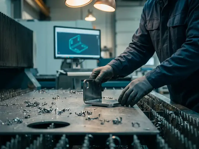
Sheet metal software focuses on the design of thin sheets that are folded, cut, and formed, with the software automatically generating unfolded drawings, cutting lists, and bending information. Structural software focuses on profiles, beams, and joints that are welded or bolted. The key difference lies in how the material is processed and what production data the software generates.
In sheet metal fabrication, it’s all about manufacturability: angles, radii, and material thickness determine whether a design can be produced. Small adjustments to a bend angle can have a major impact on the unfolded layout and, consequently, on material consumption. Sheet metal software must constantly monitor these relationships.
Structural software works differently. It focuses on stiffness, connection details, and the composition of profiles. The software calculates how beams and columns connect to each other, which bolted connections are needed, and how the structure as a whole remains stable. The production data here consists of cutting lists, drilling patterns, and welding details—not results.
What features should good sheet metal software include?
Good sheet metal software should, at a minimum, include automatic blank layout calculation, bending information for each part, integration with NC machines, and sheet metal optimization. Without these features, you’ll waste time on the shop floor and increase the risk of errors between design and production.
More specifically, these are the features you can expect from professional sheet metal software:
- Automatic flat pattern development: The 3D model is directly converted into a flat pattern, including correction for shrinkage due to bending
- Bending lists and bending specifications: For each part, the bending sequence, angles, and radii are specified for the press brake
- NC code generation: The software generates code that is ready for use in laser cutters, punch presses, or waterjet cutters
- Sheet optimization: Parts are intelligently arranged on a sheet to minimize material waste
- Parametric editing: Changes made to the 3D model are automatically reflected in all associated manufacturing documents
In addition, seamless integration with ERP systems is valuable. If the bill of materials and purchasing documents are automatically generated from the CAD model, you can significantly reduce administrative tasks.
Can a single CAD package handle both sheet metal and steel structures?
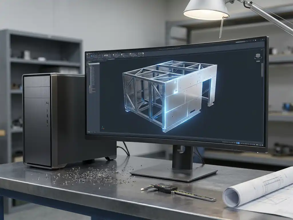
Yes, modern CAD packages can handle both sheet metal and structural steel within a single environment. The key is a flexible modeling approach that allows you to switch freely between sheet metal and structural functionality without changing environments or file formats.
In practice, this means that within the same project, you can model a steel frame and design the corresponding sheet metal parts. This is particularly useful for machines, devices, or systems in which a support structure is combined with sheet metal for covering, guiding, or housing.
Not every software package offers this combination equally well. Some software is primarily focused on structural design and includes sheet metal as a limited extension, or vice versa. Choose a package in which both disciplines are fully developed, including the corresponding production output.
How does the conversion from a 3D model to production data work in sheet metal fabrication?
For sheet metal work, the software automatically converts the 3D model into a flat pattern by calculating the bend allowance based on material thickness, bend radius, and material type. From that flat pattern, the NC code, nesting lists, and parts lists are generated directly, allowing you to move from design to production without any intermediate steps.
Calculating the results is crucial. Material stretches slightly when bent, and that stretch varies depending on the type and thickness of the material. Professional software uses K-factor tables or material-specific bending tables for this purpose, which you can link to your own press brake and material specifications.
The advantage of this direct link is that a change to the 3D model is automatically reflected in all production documents. If you adjust a bend angle, the unfolded pattern, the NC code, and the nesting list are all updated accordingly. This prevents errors and saves time during preparation.
What is the difference between parametric and direct modeling in metal design?
In parametric modeling, dimensions and proportions are defined as parameters, so that a change to a single dimension automatically updates the entire model. In direct modeling, you edit geometry freely, without relationships between parts being automatically updated. For metal design, the combination of both approaches offers the greatest flexibility.
Parametric Modeling
Parametric design is particularly effective in mass production and custom manufacturing where variations of the same product are produced. You define the basic shape once and then simply adjust the parameters. This is efficient when you regularly design similar parts with varying dimensions, such as frames, enclosures, or structures made from standard profile sizes.
Direct Modeling
Direct modeling is faster for free-form shapes, one-off parts, and situations where you want to experiment quickly without building a complete parameter structure. You simply select a face or an edge and drag it directly to the desired position. This works well when modifying imported models or in designs where the geometry takes precedence and the structure follows later.
The best CAD software packages for metalworking let you combine both approaches within the same model, so you don’t have to choose but can work in whatever way is most efficient at the moment.
What software do Dutch metalworking companies use for sheet metal fabrication and structural fabrication?
Dutch metal companies use a variety of CAD software packages, depending on their industry, company size, and production method. Commonly used options include SolidWorks, Inventor, CATIA, and IronCAD. The choice depends on the balance between ease of use, automation of production data, and the total investment in licenses and implementation.
Companies in the sheet metal industry are increasingly opting for software that minimizes the gap between design and production. Manually converting drawings to NC code or calculating blank layouts separately takes too much time and introduces errors. For many companies, automating this step is the main reason for switching software.
For construction companies, collaboration with other parties plays a major role. The exchange of IFC or STEP files, collaboration with structural engineers, and compliance with drafting standards are among the factors that help determine which software package is the best fit.
How IronCAD Helps with Sheet Metal and Structures
IronCAD is a powerful 3D CAD solution specifically designed for companies in the metalworking industry. Whether you’re designing sheet metal parts, modeling steel structures, or doing both, IronCAD provides the tools you need to move quickly and seamlessly from design to production.
Here’s what IronCAD specifically does for you:
- Automatic flat pattern and bending information: The 3D model is immediately converted into a flat pattern, including cutting lists and bending angles
- NC code generation: Using the Para-Flex add-in, you can automatically generate cutting lists, sheet optimization, and NC code—all ready for the shop floor
- A combination of parametric and direct modeling: work in the way that best suits your design, without limitations
- Suitable for sheet metal work and structural fabrication: a single environment for both disciplines, including custom work, one-off pieces, and series production
- Seamless integration with ERP: Connect IronCAD to the Dynfos ERP suite for complete automation of your production process
We support your business from start to finish: from licensing and implementation to training and optimizing existing workflows. Curious about what IronCAD can do for your metalworking business? Contact us, and we’ll work with you to find the best solution.