How can I ensure that my 3D drawing and working drawing always match?
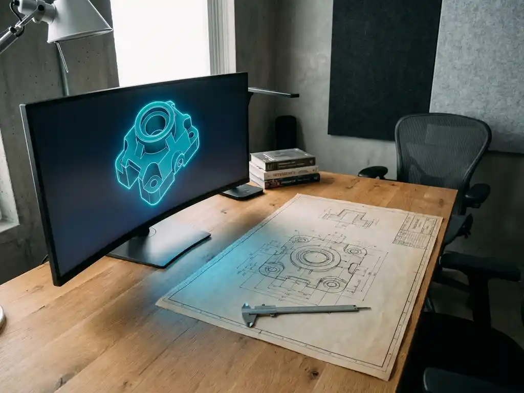
Your 3D drawing and working drawing automatically stay in sync when you work with a CAD system that maintains a direct, associative link between the two. Any change to the 3D model is then immediately reflected in all associated views, dimensions, and bills of materials. This applies to companies in the manufacturing industry that use modern, integrated CAD software. In this article, we answer the most frequently asked questions about preventing inconsistencies between your 3D model and working drawing.
Why do 3D models and working drawings so often differ from one another?
3D models and working drawings differ from one another because, in many traditional workflows, they are managed as two separate documents. A designer may modify the 3D model but forget to manually update the working drawing, or do so only later. This breaks synchronization and introduces errors that only become apparent during production.
This problem arises particularly in environments where drawings are exported as standalone files, such as PDF or DWG, and then continue to exist independently of the model. As soon as the model changes, the drawing becomes outdated without anyone immediately realizing it. In busy production environments, where multiple departments and disciplines collaborate, this risk increases significantly.
Another common cause is the use of different software packages for 3D design and technical documentation. When those tools don’t communicate with each other, a human intervention is always required. And human interventions inevitably lead to errors sooner or later.
What is an associative link between a 3D model and a drawing?
An associative link is a direct, automatic connection between a 3D model and its corresponding working drawing, so that any geometric change made to the model is immediately reflected in all views, dimension lines, and annotations in the drawing. No manual intervention is required to keep the drawing up to date.
In practice, this means that when you adjust a dimension in the 3D model, the drawing reflects this immediately. Views are automatically updated, dimensions adjust accordingly, and cross-sections remain accurate. This eliminates the most common source of errors: manual synchronization between the design and the documentation.
A strong associative link also works in the other direction. Some CAD systems allow you to enter dimension changes directly into the drawing, after which the 3D model is automatically updated. This gives designers and drafters the freedom to work in the environment that is most efficient at that moment.
How does IronCAD automatically ensure consistent drawings?
IronCAD manages the link between the 3D model and the working drawing fully automatically through an integrated drawing and modeling environment. Changes to the 3D model are immediately reflected in all linked drawing sheets, including views, cross-sections, dimensions, and parts lists. Manual updates are not necessary.
What sets IronCAD apart is its approach that does not require a history tree. Traditional CAD systems force you to undo and rebuild changes through a fixed sequence of design steps. IronCAD uses a direct, flexible modeling method that allows you to modify any part at any time without breaking the link to the drawing.
In addition, IronCAD automatically generates the output that manufacturing teams need: cutting lists, bill of materials, reports, sheet metal optimization, and NC codes. All of this output is always based on the current status of the 3D model, minimizing the risk of inconsistencies between the design and the manufacturing documentation.
Which CAD practices help prevent errors during design changes?
You can prevent errors in design changes by adopting a workflow in which the 3D model is the single source of truth and all derived documents—such as working drawings, bills of materials, and production output—are automatically generated from that model. Manual copying steps are the biggest risk factor and must be eliminated.
Specific practices that prevent errors:
- Always work from the 3D model and generate drawings directly from that environment; never as a standalone document.
- Lock final revisions before sending them to the production floor to avoid any confusion about which version is valid.
- Use parametric dimensions in your model so that changes to a single dimension are automatically reflected in dependent geometry.
- Avoid exporting drawings as static files as long as the design is not yet final. Work with live-linked files as much as possible.
- Establish a revision protocol in which every model change has a documented reason and the corresponding drawings are automatically updated before they are released.
These practices are not merely technical in nature. They also require discipline within the team and clear agreements about who is responsible for approving revisions. Proper training plays an important role in this regard.
What are the consequences of inconsistent drawings in production?
Inconsistent drawings lead to errors in production that are costly to correct: incorrectly cut material, improperly assembled parts, delays in the schedule, and unbudgeted rework. In the worst-case scenario, an error reaches the end customer, resulting in reputational damage.
The impact is greatest when the error is discovered late in the process. An error that’s already present in the cutting list leads to material waste. An error that isn’t discovered until assembly not only wastes material but also costs labor time and delays delivery. In the manufacturing industry, where margins are often tight, these types of errors can directly undermine the profitability of an order.
In addition, inconsistent drawings undermine trust within the production team. When employees know that drawings are not always accurate, they start checking and interpreting them on their own. This leads to additional communication, delays, and sometimes new errors resulting from assumptions.
When is it time to switch to an integrated CAD solution?
It’s time to make the switch if you regularly encounter production errors that can be traced back to outdated or inconsistent drawings, if design changes require many manual steps to implement across all documents, or if your team spends more time checking than designing.
Other signs pointing to the need for an integrated solution:
- Drawings and 3D models are stored in different files or systems that do not communicate with each other.
- Revisions are tracked using filenames or email instead of a version control system.
- Production output, such as NC codes or cutting lists, is created manually from the drawing rather than automatically from the model.
- It takes new employees months to understand the current CAD workflow and apply it correctly.
- You’re losing orders or customers because you take too long to respond to requests for changes.
If you recognize several of these situations, the question isn’t whether you should switch, but when. The longer you wait, the more mistakes and inefficiencies will pile up.
How IronCAD Helps Keep Your 3D Drawing and Working Drawing in Sync
IronCAD solves the problem of 3D drawings and working drawings that are out of sync by fully integrating both into a single work environment. You always work from a single source of truth: the 3D model. All derived documents are automatically updated.
Specifically, IronCAD offers:
- Automatic linking between the 3D model and the working drawing, so that any changes are immediately reflected in all views and dimensions.
- Flexible modeling without a history tree, allowing you to make changes at any stage of the design without breaking any links.
- Automatic generation of production output, including cutting lists, bill of materials, sheet metal optimization, and NC codes, always based on the current model.
- A steep learning curve, so your team can be productive within days and consistently apply the methodology.
- Seamless integration with ERP processes, ensuring that design and operations are aligned.
Would you like to see how IronCAD works in practice for your production environment? Contact us for a no-obligation demonstration.