How do I calculate the correct radius when bending steel?
To calculate the correct inside radius when bending steel, multiply the plate thickness by a material-specific factor, which is typically between 0.5 and 2 times the plate thickness. For standard structural steel, the rule of thumb is a minimum inside radius of 1 times the plate thickness. The exact value depends on the material type, the bending direction relative to the rolling direction, and the desired accuracy of the final product. In this article, we answer the most frequently asked questions about bending radii for steel, ranging from basic calculations to preventing cracks.
What factors determine the minimum bending radius of steel?
The minimum bending radius of steel is determined by four main factors: the plate thickness, the tensile strength and ductility of the material, the bending direction relative to the rolling direction, and the quality of the cut edges. The stronger and less ductile the steel, the larger the minimum radius must be to prevent cracking.
Softer steels, such as S235, can accommodate smaller radii than higher-strength steels, such as S355 or Hardox. Ductility—the degree to which a material can deform without breaking—is the key property here. In metalworking and sheet metal fabrication, it is essential to know the material properties in advance, because a radius that is too small will immediately lead to hairline cracks or worse.
The bending direction also plays a major role. Steel is rolled during production, which creates an internal grain structure. If you bend perpendicular to the rolling direction, the material is more flexible and you can use a smaller radius. If you bend parallel to the rolling direction, the risk of cracking is greater, and you’ll need to increase the radius. Always check the rolling direction before determining a bending sequence.
How do you calculate the bend radius based on sheet thickness?
A reliable basic calculation for the minimum inside radius is: R min = factor × plate thickness (t). For mild structural steel, use a factor of 0.5 to 1. For high-strength or hardened steel, this factor increases to 2 or higher. With a plate thickness of 3 mm and a factor of 1, the minimum inside radius is therefore 3 mm.
This formula gives you a starting point, but in practice there are additional considerations. The die geometry of the press, the V-opening of the die, and the bend angle all influence the result. A wider V-opening generally results in a larger effective radius, even if the die itself is sharper.
To ensure precise production, experienced sheet metal workers recommend always bending a test piece before starting a production run. Minor variations in the material batch, hardness, or thickness can affect the actual radius. Record the results and use them as a reference for similar materials in the future.
What is the difference between the inner radius and the outer radius in sheet metal work?
The inner radius is the radius on the inside of the bend, measured on the concave side of the material. The outer radius is the radius on the outside, on the convex side. The difference between the two is equal to the sheet thickness: outer radius = inner radius + sheet thickness (t).
The technical drawing and design almost always specify the inner radius, because it directly determines manufacturability and is the most critical factor in tool selection. The outer radius is relevant to the final dimensions of the product and to the calculation of the flat pattern.
When calculating the flat-out dimension, you use the neutral line, which is located at a certain distance from the inside of the bend. That distance depends on the sheet thickness and the radius. The smaller the radius relative to the sheet thickness, the closer the neutral line is to the inside. A correct deflection calculation is essential to prevent a product from turning out too large or too small after bending.
How does springback affect the final radius?
Springback is the material’s tendency to spring back after bending, causing the final angle to be greater than the set bending angle. This means you must always bend slightly beyond the desired final angle to compensate for the springback effect. The degree of springback depends on the material’s tensile strength, the radius, and the sheet thickness.
A higher tensile strength results in greater springback. With S355, the springback is noticeably greater than with S235. A larger radius relative to the plate thickness also increases the springback effect. In practice, the compensation ranges from a few degrees for mild steel to more than ten degrees for high-strength steel or large radii.
Experienced sheet metal workers determine the compensation value based on experience and test pieces. Modern CNC-controlled press brakes can automatically account for springback. However, when working with new materials or unfamiliar suppliers, it is always wise to produce a test piece and measure the springback before starting production.
How do you prevent cracks when bending steel?
You can prevent cracks when bending steel by observing the minimum bend radius, choosing the correct bending direction, and ensuring that the cut edges are smooth and burr-free. Burrs or rough edges on the outside of the bend act as stress concentrations and are a common cause of cracks.
- Keep the radius above the minimum: Always use the calculated minimum radius as a lower limit, not as a target value.
- Bend perpendicular to the rolling direction: This gives the material more room to stretch and reduces the risk of tearing.
- Remove burrs before bending: Make sure the cut edges are smooth, preferably deburred or lightly chamfered.
- Avoid using tools that are too sharp when working with small radii: A punch that is too sharp can place excessive stress on the material in certain areas.
- Check the material certificates: Use steel with the appropriate elongation values for the intended bending operation.
For complex geometries or multiple consecutive bends, it is advisable to carefully plan the bending sequence. Sometimes it is necessary to select a larger radius than the minimum to ensure the manufacturability of the entire part.
How does CAD software help with the automatic calculation of bend radii?
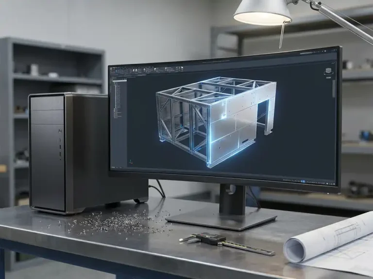
Modern CAD software automatically calculates bend radii, flat patterns, and bending information based on the 3D model and the entered material parameters. This eliminates manual calculation errors and ensures that the design and production are always aligned.
How IronCAD Helps with Steel Bending
IronCAD, the 3D CAD software that we offer as an official distributor via ironcad.eu, is specifically designed for sheet metal and metalworking. The software directly converts your 3D model into production data, allowing you to move from design to the shop floor without any extra steps. Specifically, IronCAD offers the following features for this application:
- Automatic blank calculation: The model is immediately converted into a flat blank with correct bend allowances, based on the material parameters and bend radii you have set.
- Direct bending information: Bending lines, bending angles, and bending sequences are automatically generated, ready for the press brake.
- 3D Visual Inspection: Adjust a radius and immediately see the effect on the final product, allowing you to identify manufacturability issues early in the design process.
- Para-Flex add-in: Automatically generates sheet metal optimization and NC codes that are ready for use on the shop floor.
- Suitable for one-off and series production: Whether you’re working on custom projects or series production, IronCAD adapts to your workflow.
Would you like to know how IronCAD can speed up your design and manufacturing process? Contact us, and we’d be happy to discuss the possibilities for your company.