How do I optimize sheet metal based on my machine design?
To optimize sheet metal layout as part of the machine design process, export the sheet metal parts from your 3D model, combine them in an optimization tool, and automatically generate a cutting list and NC code. This process saves material, reduces manual labor, and minimizes the risk of errors between design and production. In this article, we answer the most frequently asked questions about this process, step by step.
What is sheet metal optimization, and how does it work in a CAD environment?
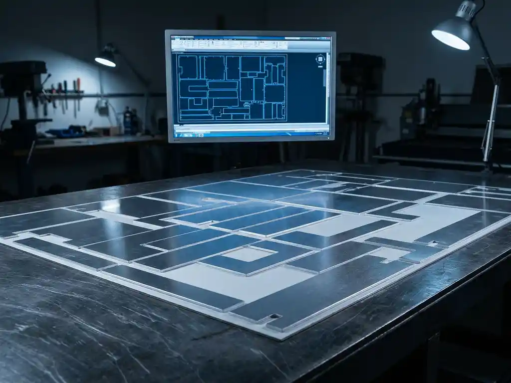
Sheet optimization is the process of arranging sheet parts as efficiently as possible on a sheet size to minimize material waste. In a CAD environment, this is achieved by automatically analyzing the geometry of individual parts and nesting them on a virtual sheet, taking into account dimensions, material type, and cutting width.
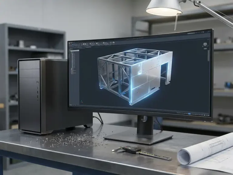
This is particularly relevant for machine-building companies. Custom-built machines often consist of dozens or even hundreds of sheet metal parts, and manually figuring out the best way to arrange them on a sheet not only takes time but also frequently leads to errors. An integrated optimization tool within the CAD environment removes that step from the manual process and places it directly into the digital workflow.
The integration between CAD and sheet metal optimization also ensures that changes to the design are immediately reflected in the optimization. If you adjust a dimension in your 3D model, you don’t have to manually restart the nesting process. The software detects the changed geometry and automatically recalculates the layout.
How do you export sheet metal parts from a 3D mechanical design?
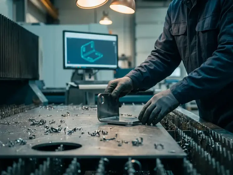
To export sheet metal parts from a 3D machine design, select the relevant parts and export them as 2D flat geometry, typically in DXF or DWG format. This process, also known as “unfolding,” automatically converts a folded sheet metal part into its flat form, ready for nesting and production.
Proper unfolding requires accurate material definitions in your 3D model. Consider sheet thickness, bend radius, and the material’s elongation factor. If these parameters are correct in the model, the flat pattern will also be correct. That is the foundation for reliable sheet metal optimization.
When exporting, be sure to group the parts by material type and sheet thickness. Sheet metal optimization tools work on a per-material-combination basis, and by sorting the parts during the export process, you’ll save time in the next step. Also, give the files clear names that correspond to your bill of materials, so that linking them to your production schedule later is easy.
What data do you need for effective plate optimization?
For effective sheet optimization, you need at least the following information: the flat geometry of each sheet part, the material type, the sheet thickness, the available sheet size, and the desired number of pieces per part. Without this information, the optimization tool cannot calculate a reliable nest.
In addition to the basic data, there are additional parameters that improve the quality of the optimization:
- Cutting width (kerf): the width of the cut made by the cutting tool. This determines how much space must be maintained between parts.
- Freedom of rotation: Can a part be rotated to achieve a better fit, or does the material have a fixed orientation (for example, in the case of rolled material)?
- Scrap sheets: Do you want to save scrap material for future use? If so, the tool needs to know the minimum scrap size that is still usable.
- Priority by component: For rush orders, it may be helpful to give certain components priority in the nesting process.
The more complete and accurate this data is, the fewer manual corrections will be needed after optimization. So be sure to invest time in properly configuring material libraries and standard plate sizes within your software.
How does IronCAD automatically generate a cutting list and NC code?
Within the IronCAD environment, add-on modules can automatically generate a cutting list and NC code based on your 3D model and sheet metal optimization. The software reads the nested geometry and translates it directly into machine-readable instructions, without requiring any manual programming.
The cutting list provides an overview of all parts to be cut, including material, thickness, dimensions, and quantity. This document serves as a means of communication between the engineer and the workshop. The NC code is the actual machine instruction for the laser cutter, waterjet cutter, or plasma cutter.
Automatically generating this output has a major advantage: the risk of typos or translation errors between design and production is virtually zero. The code comes directly from the model, not from a manually transcribed document. In mechanical engineering, where tolerances are tight and errors can be costly, this is a significant advantage.
What are the benefits of sheet metal optimization for machine builders?
Sheet optimization offers machine builders three direct benefits: less material waste, shorter lead times, and fewer production errors. Because parts are efficiently arranged on the sheet, material consumption is reduced, and because the process is automated, less time is wasted on manual labor.
In mechanical engineering, machines are often built in small batches or even as one-off units. This means that each order requires a fresh round of optimization, and the benefits of automation are felt anew with every order. Companies that perform this process manually find that engineers spend a significant portion of their time on tasks that software can complete in seconds.
In addition, sheet metal optimization has a positive effect on communication with suppliers. An optimized cutting list with the corresponding NC code can be used immediately by a laser cutter or sheet metal fabrication company. There’s no need to send separate drawings or provide verbal explanations. This shortens turnaround time and reduces misunderstandings.
How do you integrate sheet optimization with your ERP system?
You can integrate sheet optimization with your ERP system by automatically forwarding the output from the optimization tool—such as the cutting list and purchase list—to the purchasing and production planning modules in your ERP. This eliminates the need to enter data twice and keeps design and operations in sync.
The integration works best when CAD and ERP use the same part numbers and material definitions. If a sheet metal part in the CAD system has a part number that matches a purchase item in the ERP, the software can automatically create a purchase order as soon as the cutting list is approved.
This integration is particularly valuable for machine builders who work on a project-based basis. Each machine project has its own bill of materials, its own material consumption, and its own schedule. An integrated environment ensures that all this information is available in one place, from the initial design sketch to the final invoicing.
How IronCAD Helps with Sheet Metal Optimization in Mechanical Engineering
IronCAD offers machine builders a comprehensive environment in which design and manufacturing flow seamlessly into one another. With additional modules, you can work on sheet metal optimization directly from your 3D model, without having to manually transfer data to a separate program. These are the key features:
- Automatic unfolding: sheet metal parts are converted directly from the 3D model into a flat geometry, ready for nesting.
- Integrated sheet optimization: The nesting module efficiently arranges parts on the sheet, with adjustable parameters for material, cutting width, and rotation.
- Automatically generated cutting lists and NC codes: the output is ready for use in the workshop or by a subcontractor, without any manual intervention.
- Integration with Dynfos ERP: cutting lists and purchase lists are automatically transferred to the accounting system, ensuring that design and planning are always aligned.
- Change Management: If you make a change to a component in the design, the optimization is automatically updated, which prevents errors caused by outdated documents.
Would you like to know how this works in practice for your situation? Contact us, and we’d be happy to show you what IronCAD can do for your machine design.